
The company attaches importance to the role and training of technical talents, actively introduces foreign technical experience,and through the perfect quality management system certification, production of marketable high and new, sharp products, thus in a variety of fuel, rice, wheat, corn, and other areas of the processing machinery and equipment have domestic advantage.

Ⅰ. Definition of centrifugal fan
The centrifugal fan is a machine that relies on the input mechanical energy to increase the gas pressure and discharge the gas. It is a driven fluid machine. Centrifugal fans are widely used in grease factories, mainly including:
1. Ventilation and dust removal: used for oil cleaning, meal/hull crushing, ventilation and dust removal in the process of oil/meal transportation;
2. Pneumatic transportation: such as the wind transportation of bean skin, the transportation of white clay, the wind separation of skin/kernel, and the transportation of coal ash;
3. Ventilation and drying: such as the induction air of the conditioning tower, the drying/cooling of the puffed material, the drying/cooling of the meal, etc.
Ⅱ. Principle of centrifugal fan
When the impeller rotates with the rotating shaft, the gas between the blades also obtains inertial centrifugal force with the rotation of the impeller, and the gas is thrown out from the outlet between the blades. The thrown out gas squeezes into the casing, so the pressure of the gas in the casing increases, and is finally directed to the outlet to be discharged. After the gas is thrown out, the pressure in the center of the impeller drops. Outside air can be sucked in from the suction port of the fan through the orifice in the center of the front disc of the impeller, and the gas is continuously delivered.
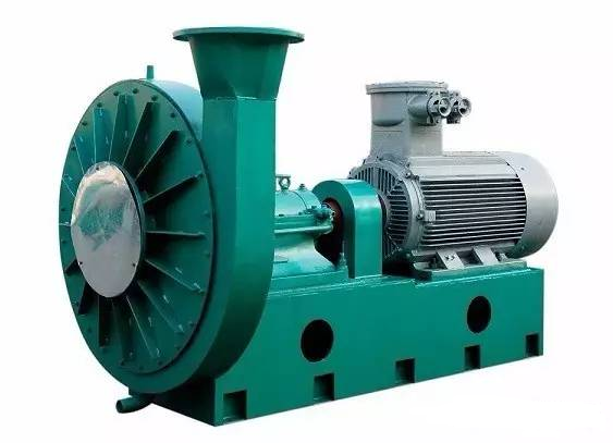
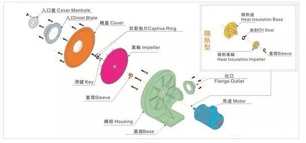
Ⅲ. The structure of the centrifugal fan
The centrifugal fan is mainly composed of impeller, casing, air inlet, regulating air door and driving device.
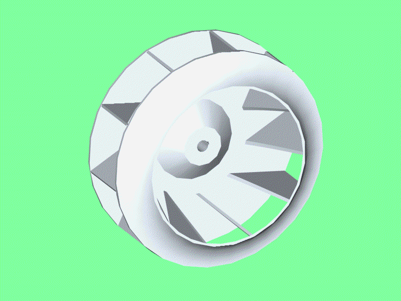
Impeller: It consists of a front disc, a rear disc and the blades installed between the two discs.
Casing: The casing of the fan is volute-shaped, welded with thin steel plates, and its function is to collect the gas from the impeller, and make it smoothly be guided to the outlet of the fan along the direction of rotation of the impeller, and pressurize the gas .
Air inlet: The head end of the suction pipe section plays a role of collecting air, so it is also called a collector.
Ⅳ. main performance parameters
Flow rate Q: The amount of fluid transported by the fan per unit time, usually expressed by volume flow, in m3/s or m3/h, which is related to the structure, size and speed of the fan.
Pressure head p: the effective energy provided by the fan to the unit volume flow, the unit is pa.
Efficiency η: In the actual operation of the fan, due to various energy losses, the actual (effective) pressure head and flow rate are lower than the theoretical value, and the input power is higher than the theoretical value. The parameter that reflects the magnitude of energy loss is called efficiency. The efficiency is related to factors such as the type, size, processing accuracy, gas flow and nature of the fan. Generally, the efficiency of a small fan is 50% to 70%, while that of a large fan can reach 90%.
Shaft power N and effective power Ne: Shaft power is the power of the motor input to the fan shaft in W or kW. The effective power of a centrifugal fan refers to the energy obtained by the gas from the impeller in a unit time, and Ne=Qp, N=Ne/η=Qp/η.
Speed n: The number of revolutions per minute of the fan and fan impeller is "r/min".
Ⅴ. Use and operation of the fan
1. Preparation before starting the fan
1) Close the regulating air door, and close the air inlet and outlet doors of the fan;
2) Manually crank, check the gaps between the components of the fan, rotate the impeller and the casing to see if there is friction;
3) The coupling and pulley protection passport are installed in place;
4) Whether the oil level of the bearing box meets the lubricating oil level during operation;
5) For fans with water-cooled bearings, check whether the water supply of the cooling water pipe is good;
6) Determine the rotation direction of the fan electrically, and check for water leakage, oil leakage, vibration, abnormal noise, and odor.
2. Start of the fan
1) Start the fan (pay attention to whether the operation is stable);
2) After the fan is started, gradually open the large damper until the actual air volume required for production; pay attention to the running current of the motor when opening the large damper to prevent the excessive opening of the damper from causing the fan to overload;
3) The temperature of the fan bearing should be checked after starting, and the temperature rise of the bearing should not exceed 40 degrees of the ambient temperature of the site;
3. Inspection of the fan during operation
1) Listen to whether the fan is running smoothly, whether there is abnormal noise or friction;
2) Check whether the anchor bolts are loose;
3) Detect the temperature and lubrication of the bearing;
4) Whether the bearing lubricating oil cooling water is unblocked, and whether there is a temperature difference between the inlet and outlet pipes;
5) Whether there is lubricating oil leakage in the bearing box;
6) Whether there is abnormal noise in the bearing housing and bearing operation, and whether the rotation is stable;
7) Check whether the current operation is stable.
4. Emergency stop
1) It is found that the fan is making violent noises;
2) There is friction between the impeller and the casing;
3) The vibration of the case suddenly intensified;
4) The bearing temperature continues to rise and exceeds the allowable temperature rise range;
5) The sudden increase in current cannot be restored within 2 minutes;
6) Serious oil leakage in the bearing box;
7) The cooling water is interrupted for more than half an hour.
5. Fan shutdown
1) Stop the fan operation after reducing the load;
2) Close the cooling water inlet and outlet valves;
3) If the hot air is being transported, the fan should be stopped after the heater is stopped and the temperature of the fan's air outlet drops to 40 degrees;
4) After the fan is shut down, open the drain valve at the bottom of the casing for drainage; at the same time, close the fan inlet and outlet dampers.
Ⅵ. Precautions for the selection of the leaching fan in the leaching workshop:
The fans in the leaching workshop include the fan FN300 for the immersion scraper, the fan for mineral oil FN361, the fan FN305 for the DTDC, and the sweeping fan FN381 for the leaching workshop. In addition to meeting the technological requirements, the fan must also be explosion-proof. The fan should not be driven by belts. For transmission, the fan speed should not exceed 1440RPM.
Copyright © Henan Zhongxing Grain And Oil Machinery Co.,Ltd. All Rights Reserved. Powered by MetInfo